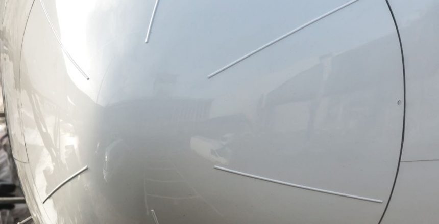
Lightning protection for weather nose radomes does NOT have to be complex. This article is essentially a handbook to help you get everything you need for your design – all major documents and many of our in-house resources are found here.
If you’re a radome design engineer, you’re probably wondering how to protect your composite radome from lightning damage, to be compliant with FAA regulations. FAA 14 CFR 25.581 and other regulations can be quite confusing and technical.
If you’re looking for practical information about lightning protection for weather nose radomes, including lightning zones, FAA regulations, or how to calculate the diverter size you need to prevent melt-through, keep reading.
Radome Lightning Protection Basics
What type of lightning strike does your radome need to withstand? Allen explains here.
How often do lightning strikes occur?
Actually, quite often.
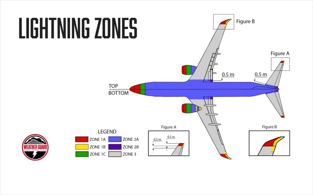
Anytime a commercial aircraft is flying around a thunderstorm, it’s quite possible to see lightning activity on the nose radome. Nose radomes are located in Zones 1A or 1B (see below) – the areas most likely to see the most lightning activity.
In order to be approved, your radome (or any part) must be in compliance with regulations:
FAA Lightning Regulations:
- 23.867
- 25.581
- 27.610 and/or
- 29.610 (and possibly the corresponding systems regs)
to ensure its airworthiness, specifically its ability to withstand a catastrophic lightning strike. The industry standard “catastrophic” strike accepted by the FAA and EASA is a 200,000-amp strike.
For an in-depth tutorial on 14 CFR 25.581 FAA regulations for lightning, read our article here or watch the presentation below:
In terms of energy, a 200,000-amp strike equates to a two million action integral. A two million action integral represents the approximate specific energy of those 200,000 amps acting on your part in the half-a-microsecond-or-so that the lightning actually impacts that part of the plane – and that’s what you have to design for. We’ve simplified calculating temperature rise for copper wire below:
Use Our Temperature Rise Calculator for Various Grounding Wire Thicknesses
NOTE: This calculator is tested accurate, but is NOT a replacement for running and checking your own calculations. This is only to be used for quick information to help you speed up your design process and finding an approximation of the correct lightning protection grounding wire.
Remember: lightning protection grounding wire size is critical! If you need help with this step, give us a call.
Design Requirements: Weather Nose Radomes and Lightning Protection
While lightning strikes to aircraft are a common occurrence, the statistical likelihood that your part will receive a 200,000-amp strike is pretty low. However, there are at least two good reasons that the standard exists. The obvious reason is that major lightning strikes do occur, though fortunately, not often.
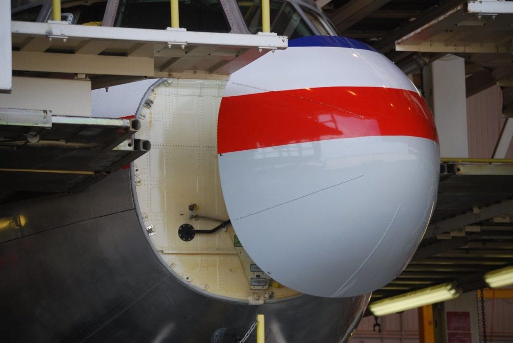
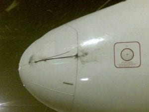
The less-obvious reason and more likely scenario is that your nose radome is going to see a lot of much smaller strikes. A lot. And while some of those lightning strikes will be so small they won’t register, each one poses danger to the part, and potentially to the aircraft performance and safety. Also, each of those smaller strikes, over time, adds up to measurable damage.
About the FAA Lightning Protection Regulations
Basically, regulations 25.581, 23.867, 27.610 and/or 29.610 require lightning protection systems to not endanger the aircraft and to safely conduct lightning current away so that it doesn’t damage the plane. While each section is specific to certain aircraft (Section 23 specifies requirements for small aircraft, Section 25 for larger aircraft; Section 27 for small helicopters; Section 29 for larger helicopters), the FAA language for each type of craft states essentially the same thing:
“The airplane (or rotocraft) must be protected against catastrophic effects from lightning.”
– Aircraft Lightning Protection Handbook, Federal Aviation Administration
So the requirement is clear, if not very specific: the part must be able to handle the statistically largest strike it may experience. The types of strikes it is likely to experience depends on myriad factors, including materials used, design, and attachment zone.
Weather nose radomes, almost without exception, are installed in attachment Zone 1A. Parts in Zone 1A must be able to withstand a 200,000-amp strike, and they submitted to extensive testing before approvals are granted.
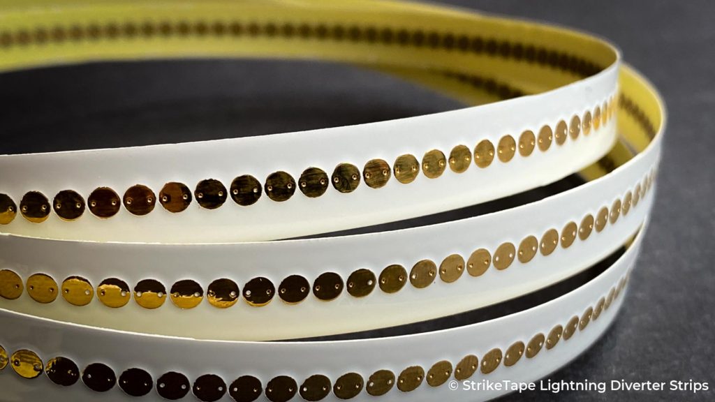
Tests take into account the complete and finished part, including its structure, composite materials, and protective coatings. In other words, the entire design – and every detail – affect your part’s approval and ultimate airworthiness.
To answer specific questions – like how big does my wire (lightning diverter) need to be, and how well-grounded? – you’ve got to do the math.
Do the Math to Prevent Melt-Through of Lightning Protection Grounding Wires
If lightning strikes your part, the current has to go somewhere. The point of lightning diverters (on radomes) is to protect the radar, first and foremost, and then to minimize damage overall. So, your diverter needs to be big enough to handle the current and action integral of a lightning strike on the 95th (99) percentile, that is, the 200kA, 2m action integral.
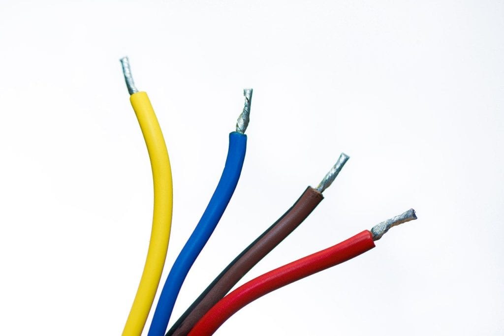
Using the appropriate calculations, you can find the temperature rise of the wire in your design and determine when or if it’s likely to approach the melting point.
No matter how well designed your radome and lightning protection, aircrafts encounter lightning that will damage carbon fiber composite or reinforced plastic (CFC/CFRP) parts. And repairing complex parts is a pain, but it can be done.
Minimizing overall damage – to your radome and the rest of the aircraft – is the goal.
We Can Help You Complete Your Radome Design
Here at Weather Guard we’ve been designing lightning protection for radomes for 25 years. All of our products meet the industry’s maximum requirements. If you need help with your radome, give us a call today.
About the FAA’s Lightning Zones and Definitions
For the purpose of protection design, there are defined lightning zones on aircraft where the external environment is applied to the aircraft. When the environmental element is lightning, zones identify where lightning is likely to attach, unlikely to attach, and others which will be exposed to attachment for only a small portion of the total flash duration.
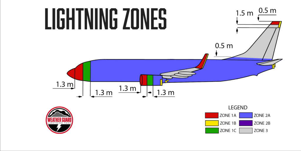
The precise location of each lightning zone depends on each aircraft’s geometry, materials and operational factors, so zones can vary from one aircraft to another.
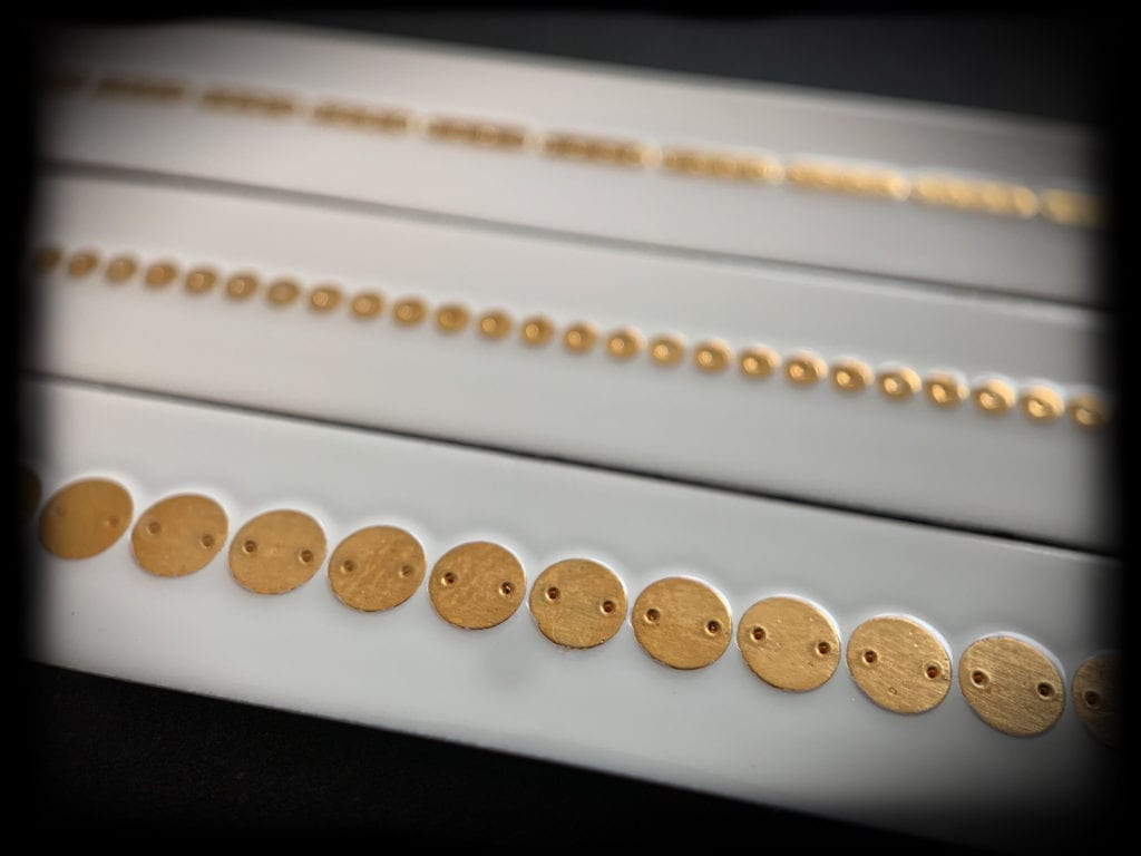
Zone definition is somewhat subjective, and a determination must be made for each aircraft configuration.
Actual zones are usually established by the aircraft designer by reference to past inflight experience with aircraft of similar design or with the aid of lightning strike tests on scale models.
Breakdown of FAA Lightning Zoning
For purpose of protection design, the in Advisory Circular AC 20-53A [3.21], the FAA created the following lightning zones and definitions:
- Zone 1A: Initial attachment point with low possibility of lightning channel hang-on.
- Zone 1B: Initial attachment point with high possibility of lightning channel hang-on.
- Zone 2A: A swept-stroke zone with low possibility of lightning channel hang-on.
- Zone 2B: A swept-stroke zone with high possibility of lightning channel hang-on.
- Zone 3: Those portions of the airframe that lie within or between the other zones, which may carry substantial amounts of electrical current by conduction between areas of direct or swept stroke attachment
Questions About Your Radome Design or Lightning Zone?
More helpful resources:
- How Does the Boeing 757 Lightning Protection System Work?
- How-to Guide to FAA 14 CFR 25.581 Compliance
- EASA CS 25.581 Compliance Guide
Need Radome Design Help?
Give us a call today! We love helping radome design engineers.

