In this video tutorial on EASA 25.581 (which includes subtitles and a full transcript below), you’ll learn FAA DER Allen Hall’s 5 key steps for reaching lightning protection design compliance. Be sure to check out our lightning protection regulations page for more guidance.
Need Help with FAA 14 CFR 25.581 Regulations? We’ve got you covered in this tutorial guide on FAA 14 CFR 25.581.
VIDEO TRANSCRIPT: EASA 25.581 – A Guide To Lightning Protection Compliance
I’m Allen Hall, President and CEO, Weather Guard Lightning Tech. In this tutorial, I’m going to discuss EASA 25.581 requirements for lightning protection, EASA 25.581. Let’s get started.
So there are really three things to remember here with the regulations it’s broken up in three parts. The first part of EASA 25.581 is part A, which is the airplane must be protected against catastrophic effects from lightning. So also see EASA CS 25.899, which is a bonding requirement. So the first criteria is you must stop catastrophic effects, pretty straightforward.
And in this image, there’s an aircraft that has clearly crashed into the runway that was due to a lightning strike from several years ago, where lightning struck the control surfaces in the back end of the airplane and the empanadas, caused some damage back there. And, and it severely degraded the pilot’s ability to land the airplane safely.
So we don’t have a lot of catastrophic incidences with aircraft and lightning strikes today, but they occasionally do have a very severe accidents, hazardous type events where lightning is damaged the aircraft. And we lose some capability of the aircraft. In this particular case, they were fortunate enough to, to put it on the runway.
But now let’s get to part B. Part B metallic component: part B is discussing metallic components specifically for metallic components compliance with sub paragraph a of this paragraph may be shown by one bonding the components properly to the airframe or to design the components of the strike will not endanger the airplane.
So there’s two images here on the left is a King air. Wingtip, which is a metallic wean tip where lightning as has attached to that wing tip and physically. Warped crushed part of the aircraft structure. Right? So electrical bonding does play into that. You want to give the lightning current someplace to go, right?
But even then you’re still structural effects that can happen on aluminum airplanes. And just to the right of that is a image or a typical lightning attachment location where it melts a rivet head or melts a small port of the metallic surface of the aircraft. Okay. So those are two sort of extreme examples, right?
Of a typical lightning attachment and a severe lightning attachment. So let’s go to non metallic component, which is covered in, in part C. For non-metallic components compliance with sub paragraph a of the paragraph may be shown by one, designing the components to minimize the effect of a strike or to incorporating a subtle means of diverting the resulting electrical current.
So as not to endanger the airplane. So I provided two pictures here for part one, we’re showing any composite wing tip may not have carbon fiber that has expanded metal foil on it. So they’ve designed the component with the expanded metal foil to minimize the effect of a strike, to prevent maximum damage to the composite structure.
So the metal foils are carrying some of the lightning energy away from the composite surface. So that’s a way to minimize the effect of a strike. The other one, part two, which just shows up as it’s an antivirus rate home with a copper bar on the radon. That’s a means of diverting electrical current. So the copper bars provide a pathway for lightning to travel away from the non-conductive fiberglass, Kevlar nose of the Airbus airplane.
All right. So those are your two different examples there. So diverting the current or incorporating an acceptable means to carry the current. Alright so that’s the regulation. Now there’s a, there’s a number of pieces of guidance material that you will need to acquire to help you through this certification effort for EASA 25.581.
Let’s take a look at those. There are four documents. And those four documents from Euro. Okay. And SAE has equivalent documents, but you can find the Eurocae ones online. So ED113 aircraft lightning director. Perfect certification. Yeah, 80, 91, a lightning zoning aircraft lightning environment and related test wave forms, and then eating one Oh five, a aircraft link test methods.
So each one of those has a specific piece of information you’re going to need for compliance for CS 25.581. So you need to gather the whole group there. So what is the process to show compliance to 25.581? Well, it’s outlined in ED113. And I’ve broken it down into five steps. It sort of simplified it a little bit because this is the process that I usually follow.
Otherwise you can get a super complicated and detailed and very specific steps, but in general, this is the process to follow step one, determine the lightning strike zones for the aircraft. Step two, establish a lightning environment. Step three, perform a lightning hazard assessment, step four, design the protection and step five, verify compliance.
So let’s, let’s walk through each one of those in detail. So you can see how each one of those little steps gets performed. So step one, lightning strikes zones ED91A is going to contain that information and it’s going to discuss each of the different lightning zones that apply to particular parts of the aircraft and different types of aircraft.
So it explains lightning zones for rotorcraft helicopters, for jet jet aircraft, where the engine or Mount on the fuselage or jet aircraft where the, the engines are mounted on the wing and basically different sizes of aircraft. And different configurations, they also include turboprops in that discussion, but. we need to define where likely lightning is lead to attach, because it has specific implications for the amount of damage that you’re likely to see on that particular component. So in general, there are three zones. So in one, which tends to be the extremities, the wingtips, the tail tips, the nose zone two.
And, and that has a, a maximum current applied of 200,000 amps- lightning zone two- which tends to be the fuselage of most aircraft, some parts of the wing, some parts of the tail, but sort of the middle of the aircraft that has a maximum current well hundred thousand amps. And then zone three is everywhere else, which tends to be on most aircraft in the middle of the wing.
Alright. So just to get a sense of what the lightning zones are. I provided an example here, but you need to go look at for the specifics. Step two is looking at the lightning environment. The lighting environment is defined in . And so it takes those, those zones on one’s own twos on three and applies energy to them to evaluate damage.
So just as a rule of thumb here, lightning zone one is a 200,000. Wasn’t me up to strike with current components, A, B and C, and there’s those voltage affects that. Go along with it, but we’re going to simplify it here and just talk about the high, current part of it. The damaged part of it, a lightning zone two, which is 100,000 amps, which is components, DB.
And see if you look in the spec and then lightning zone three, which is a 40 kiloamp strike, which has components that are 5B and C. So just in general, just so you know. So the, the wingtips and the nose and the tail. Extremities need to be designed to handle 200,000 amp strikes the main body of most aircraft, the fuselages need to be designed to handle 100,000 amps in lightning zone two.
And then those odd things that are on lightning zone three and Ebo handle 40,000 amps. Okay, so that’s step two. Now, let’s moving on to step three, the lightning hazard assessment. So we need to evaluate the likely lightning damage for aircraft structures, but also systems. And when I say systems, I’m not talking about avionics displays, but more importantly, like control tubes, control, rods, things that are mechanical nature that are located typically out towards extremities, flap, actuators, things of that sort, when, which if lightning struck near them or lightning attached to the flapper, an aileron there could be subsequent effects.
Inside the airplane, there wouldn’t be a direct strike sort of situation, but the, the effects of carrying large amounts of current could do damage and affect the aircraft performance. Right? So we’re looking for catastrophic effects, a failure or a malfunction, and that can happen immediately. Like, if you severed a control cable or it could have some other delay could be a delayed effect.
So if you were to damage a composite of structure, but to continue the flight, you overloaded that structure because it’s been weakened from the lightning strike, that would be a delayed effect. And you still have to consider that. So. As were going through that evaluation, you had really different determine what primary structure is for the aircraft, because those are the ones who really need to pay attention to cause primary structure.
If you damage primary structure, you’re essentially going to lose the aircraft, but 25.571. From the FAA side. If you want to go look there, there’s a similar EASA requirement for primary structure and then AC 25.571, which is the FAA requirement. There’s also guidance from EASA to to just to look at primary structure and what that is for most lightning engineers.
We, the electrical people, we don’t really know primary structure is. My advice is to talk to the structures groups at the aircraft companies that you’re working with to determine what. His primary structure to understand what those primary structures are, so that you’re working on the right thing and focusing your energies and time on the right.
Parts of the aircraft continuing with the lightning hazard assessment. We’re gonna look at structural components that includes fasters and major structural joints control surfaces, pushrods cables, actuators hinges, bond jumpers, externally Mount of components like antennas and Ray domes. We’re also going to look at loss of system function like in you lose the effect of, aircraft power, for example.
So you take a strike to the structure and you’re near a big power cable and it damages the power cable. That’s a subsequent effect, but you need to be looking at that as an effect on the aircraft that is due from a lightning direct effects, strikes. So even though the regulation, this is really focused on structures, you need to also be looking on the effects of systems.
So you don’t have a subsequent effect, which, and then endangers the aircraft. Right. And then in particular, I think a good place to sort of help you put all this together and provide a thought process on how to evaluate it. Is an AMC, which is an acceptable means of compliance 25.1309. So yeah, and there there’s, you can use it to create a basic 1309 type assessment, but we’re going to consider it a lifetime safety classification.
It’s not a probabilistic assessment, it’s a qualitative assessment. But we need to look at those pieces of hardware and components on the aircraft that could be affected by a direct strike. And determine whether the direct strike can affect aircraft safety. Okay. Moving on to step four design protection for metallic components.
Okay. So we’re looking at a typical materials, aluminum steel titanium, things are used typically in aircraft. We want to look at cross sections thicknesses, how they’re attached is a bolted or welded. Is it riveted? Is there some adhesives? We are going to look at coatings from anodized coatings, which are non-conductive to alodine coatings, which are conductive to different kinds of paints and surface protectants.
And then we want to look at electrical bonding, right? So we worked we’re, we’re trying to make sure that when we design some piece of metal to carry lightning current, so that it has an adequate cross section that it’s connected together and the joints will be able to carry lightning current without coming apart.
Well, we designed non-metallic components, right? So when we’re designing a protection for things like fiberglass or on Kevlar or carbon fiber, we need to go look at specifically what those materials are. So a carbon fiber piece of structural have slightly different types of protection than a piece of fiberglass will.
Again, we’ll look at the. Thickness and the cross section, we’re going to look at things like metal foils conductive coatings typical things here are copper bronze, aluminum, or, yeah, in terms of expanded benefit oils and then silver, which is a very common conductive sprayed material that is applied to.
Fiberglass antic, carbon fiber. So we want to try to determine how we want to protect it. And there’s a lot of choices. This is out there. You need to really look up the literature, do some research, ask around, call us to get an idea of what, what are the likely paths, what other kinds companies have done in similar situations, because there’s a lot of data out there at this point.
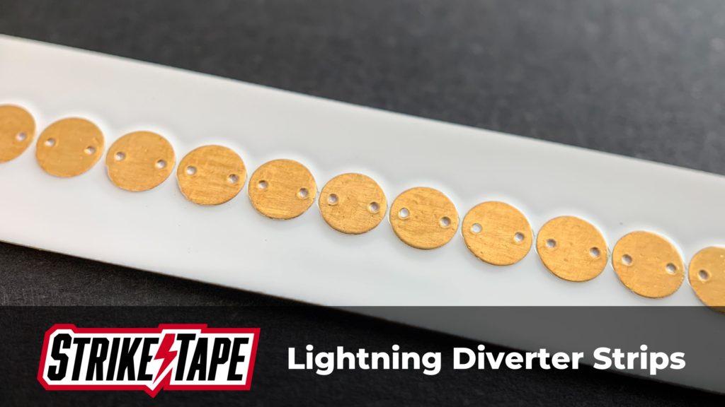
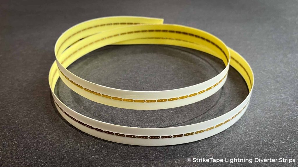
So you’re not in the blind, used to be able to define some help to guide you in what types of lightning protection are probably appropriate for your application. StrikeTape diverters, which is another way. That’s our product applying lightning diverters to aircraft radomes, very common. It just diverts the lightning current away, protects the structure. And then we also will look at how we’re attaching those non, non metallic components to the rest of the airplane. Are they bolted? Are they just screwed on? Are they adhesively bonded because we need to provide current paths from the non metallic. Structure to the next piece of structure, beat metallic or non-metallic, how are we getting the cross, those joints?
And then as part of that, we’re looking at electrical bonding, right? So those are the design details we need to be looking at as we provide any protection. All right. Step five. So once you’ve identified how you’re going to protect those parts, be it metallic or non-metallic. How do you go about justifying and showing the EASA or FAA or any other certification authority?
How you, your, your design actually functions. That is mostly done by lightning test today. There are, there are some cases where you can do it via analysis. If you have previous test data, obviously, or if you have a lot of aircraft service history, in some cases, it can be appropriate, but mostly you’re going to get us to some sort of lightning test analysis is used and I provide two pieces of information there from the FAA site, but.
There is a aircraft lightning protection handbook, which is available on the internet. And also there’s a ag lightning direct effects handbook, which has a lot of information about types of lightning damage to carbon fiber and fiberglass structures that are protected with a variety of different kinds of foils and paints and that kind of thing.
The last one that doesn’t get used as much as similarity. So similarity tends to get used where we have a metallic wing tip. When I go to use that metallic weight when tip on an Airbus 319. Okay. So there, there are similar aircraft. The designs are very similar. Therefore we can apply the results from one certification approach, one design onto the next design.
That’s where similarity tends to get used in EASA 25.581 type processes. Those are the five steps, but he also provides additional information, which is fantastic because, uh, if you’re just trying to design a component for the first time, you like to have a little bit of guidance and the acceptable means of compliance that EASA puts out.
Provides that information. So what’s, let’s walk through the acceptable means of compliance. This is not a deep thought thorough experiment evaluation of the, the, of the AMC, but just want to highlight that this information is there and how a design engineers apply that information. So the AMC 25.581, which discusses external metal parts and external metal parts should be either A–
electrically bonded to the main earth system by primary bonding pass or B– so designed and or protected that a lightning discharge to the part EG a radio Ariel will cause only local damage, which will not endanger the airplane or its occupants. Okay. So what does that mean? Well, what’s, let’s keep going down the AMC and see what that means.
So one bond, internal linkages of external parts to the airframe. All right. So they’re what they’re trying to do is get lightning currents off linkages, structural paths that are control surface related, so to speak. Screw jacks or I there’s a screw. I show a screw Jack here where there’s been bonding done to that screw Jack or a quadrant, which is the control cables, how it attaches to an aileron or an elevator or an it or a rudder where there’s a bond jumper that tries it.
Dump the currents off of the control surface back to main air frame structure, and doesn’t allow a lot of current to go down the control line, which could be damaged and create a catastrophic effect. So at the bottom, each one of these slides, as the actual words down here, I’m going to try to summarize each one of them just for the sake of time.
So a second thing, design bonding jumpers to limit current through actuators, right? So typically what you see, this is on the horizontal stabilizers of, of jets or turboprop airplanes, where they have horizontal pitch trims, that whole horizontal stabilizer is riding on an actuator.
And what they’re trying to do is provide a current path. That’s not through the actuator. Smart thing to do, okay? So I provide two examples here. This is what you see be sort of bigger bond jumpers up in the horizontal stabilizers. And there’s an example here of from a manual that shows a bond jumper going from the horizontal stabilizer to the scissors structure, that carries a current away from the actuator pretty standard designs, right?
Evaluate all flight configurations and damage to electrical system components. Now. What we’re talking about here specifically are things like electric components on the outside of the airplane, like AOA probes that are heated pitostatic probes or static ports that are heated, anything that’s sort of sitting on the outside of the airplane has power running into it because you want to prevent transient surges and things like that from getting onto the power buzzer or damaging other things in the electrical system. So when we install a heated pitot probe, we’re gonna do a lightning test on it to make sure that we do not inject current onto the power bus and damage the displays, for example.
Right? So we want to evaluate those all the flight configurations and components on the outside of the aircraft. So the flight configuration can play into a little bit when we have flaps down, there’s our components that have exposed that wouldn’t normally ordinarily be exposed and certain parts of flight deployment of landing gear, right?
So there’s, anti-skid on the landing gear. Those things are normally tucked up in the airplane, but when they are. Planes coming in and land or aren’t during takeoff, there are situations where those components are sitting out in free space and can be struck by lightning and can inject a bunch of current onto the rest of the aircraft.
So things to think about in terms of external metal parts. So external non-metallic parts. You want to provide them with some sort of diverters, right? Be it metal bars foils or StrikeTape lightning diverters. So you want to provide a pathway for lightning to go around non metallic parts if you can.
Right. But you also need to make sure that we’re designing those things properly. They’re handling amount of current for where they’re going to be installed. Right? You want to prevent damage that endangers the aircraft. So a non-conductive components, there are times in which the component, so where it is really want endanger the aircraft.
Right. And so they’re provided example here. This is C-130 or a military aircraft, U.S. military aircraft, where the little fairing at the back of the horizontal stabilizer, has been knocked off. Well that doesn’t have an effect on safety. Right? That part can come off, come clean off and
nobody really cares in terms of safety. Right? So, but if there are places where lightning may endanger the airplane, we need to make sure that we are taking care of them and making sure we identify them first and design protection for them. And then for radomes in particular. So there’s a lot of discussions about radars in the AMC when to ensure that lightning hits diverters and the governors are.
Size properly. Right? So on a nose radon. Sure. That we actually have a, if we’re using copper bars, we have an appropriate cross section of the carry, the current, you can do it by sort of analysis to get you a rough estimate of that, or just look at what other aircraft companies have done. Yeah and make sure that those parts, those diverse are in the right places on those parts on the radar.
Usually it falls up to the lightning test, right. To validate all that. So there’s a bunch of other things here and sort of the non metallic parts for EASA where they want to look at. And discuss a particular aspects to those non conductor parts. So I’m going to read through these real quickly. So we’re, non-product, we’re unprotected, non-metallic parts are fitted externally to the airplane in situations.
When we make exposed to lightning discharges e.g. radomes the risks include the following. So I provided example of pretty much all of these risks here, where the big lightning hole in a nose radome, A– that disruption of the materials because of rapid expansion of gases within them e.g. water vapor.
So water vapor inside of a radar. Honeycomb structure. Radomes tend to be fiberglass, honeycomb structure fiberglass. If you get water inside of there that in theory that water could heat up and create more damage, right? Be the rapid buildup of pressure in the enclosures provided by the parts resulting in mechanical disruption of the parts themselves or the structure and closed by them.
So what they’re saying is if you have an enclosure like a radar and you happen to puncture it, there is pressure built up inside of there from the lightning. Strike and that that part can come apart and do damage to it, to itself obviously, or to things that are around it. I see caused by ignition of the materials themselves or the materials contained within the enclosure.
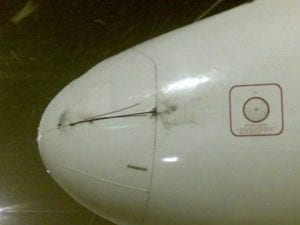
So if lightning hits the puncture, the radar, does it catch the radar on fire? Does it make the antenna or catch the antenna on fire inside things you need to evaluate? Right. So it’s very important. If you’re gonna allow a puncture to a radon, you look at subsequent effects, right? And holes in the non metallic part, which may present a hazard at high speeds.
So, this is why I provided the picture here, which is a high speed aircraft where there’s been a large hole in the radar home. You need also look at aerodynamic effects that do you over pressurize the radar to effect where it starts to come apart from the arrow loads. Right. So things to think about it for non-metallic parts.
All right. So, also for non metallic parts — EASA is very thorough about this. Now let’s walk through 2.3, 2.4 and 2.5, which is the materials you should not absorb water and should be of high dielectric strength in order to encourage surface flashover, rather than puncture laminates made entirely from solid materials are preferable to those incorporating the laminations of silly and material and sell.
There were material means honeycomb, essentially what that means. So if you build a solid piece of laminate it doesn’t have it, doesn’t want to absorb water. Which makes it a little more resilient in a lightning strike and less likely to be punctured. So the preference is to make solid structures versus honeycomb structures from a lightning protection standpoint, even though both designs are flying today very successfully.
You just need to make sure that you’re trying to prevent water from accumulating in honeycomb structures. That’s essentially what it means. 2.4. Those external non metallic parts, which is not classified as primary structures should be protected by primary conductors. Right? So what they’re saying here is that if I have a secondary structure, so a secondary structure tends to be ferrings covers things of that sort that we design them, such that we provide primary current pass on them. Right, we don’t forget about them. It doesn’t mean you can’t damage them or they can’t be damaged by lightning cause they will be, but we don’t just discard them and say, Oh gosh, you know, it’s completely, necessarily sacrificial. We’re going to provide some means of carrying the current, ideally.
So this is a way of complying with the regulation. There are different takes on this and this one can be kind of controversial quite honestly. Right. But the thought process is like, Hey, we need to do something here in terms of lightning protection and 2.5. Were damaged to an external non metallic part, which is not classified as primary structure may endanger the airplane.
The parts should be protected by adequate lightning to murders. Okay. Let’s give an example of that. If I have a large SatCom radome on top of the fuselage and lightning strike punctures that. And damages that rate on that radome comes loose and hits the vertical tail structure that could be catastrophic.
So the radome itself is not primary structure, but the subsequent affectionate lighting strike it caused damage to the aircraft, which it would not allow it to continue to say flight landing that needs to be fixed. And they’re saying you need to put lightning diverters to prevent that from happening just makes sense. It just follows the logic of the regulation. Okay. 2.6 confirmatory tests maybe required to check the adequacy of the lightning protection, providing, e.g. to confirm the adequacy of the location and size of bonding strips on a large radome. And I provided a picture here of a high voltage lightning attachment test.
So what they’re saying here is that if you have essentially a new design or an unproven design, this is where this is going, is that you want to perform some sort of lightning test on it per the guidance materials to validate it. And you, you make sure you have one that the design actually works like intended.
And two, it can handle the amount of current that it’s likely to experience in flight. Smart thing to do – it happens. Yeah. Time. There are a number of, of lightning test facilities all around the world who can provide this level of testing. Yeah so it should be readily easy to do. And. I think that the key is here is to get some advice before you get to the point of going to the lightning lab, you should be fairly confident in your design either by looking at other aircraft, talking to the lightning protection engineers, or pulling relevant data to protect the radar before you actually get to the, to the lightning lab.
So that does it for our tutorial on EASA CS 25.581. If you have lightning protection questions, check out our YouTube channel with a bunch of informational videos or visit our website at weatherguardaero.com.
Aircraft Lightning Strike Protection Resources
- SAE ARP Lightning Guidance Material: What You Need to Know
- In this article, we discuss SAE ARP 5414B, 5412B and 5416A, which are crucial documents that every radome design engineer needs in their library
- SAE ARP Guidance Material Explained [Podcast]
- In this episode of the Struck Aerospace Engineering Podcast, FAA DER Allen Hall discusses the SAE ARP documents and explains what’s contained in each and why they’re important.
- FAA 14 CFR 25.581: The Guide to Compliance
- This article contains an accompanying video presentation that walks radome engineers through compliance with FAA 14 CFR 25.581, giving examples and steps to meeting the requirements.
- The Weather Guard Help Doc Center
- Visit our archive of historical lightning protection documents, crash reports, and articles on compliance, regulations and more.
Need Lightning Protection Help?
Contact us today – we love helping engineers just like you.

